By Tom Godbey, Donaldson Torit Application Specialist, and Dan Johnson, Donaldson Torit Application Engineer
Industry consumes 27% of the retail electrical energy produced in the U.S., and fans and pumps account for 40% of that 27% -- with fans being the majority of the 40%.(Ref 1, 2) Yet, when was the last time your company conducted an air audit to see how much air you move each day and the power used to move that air? Most plants move more pounds of air than produced product, and significant energy is used in moving that air. Since energy is money, if we can save energy used for moving air, we can save money and drive down the cost of the product produced.
Air has weight and because it has weight, we need to exercise good engineering judgment when dealing with exhaust systems. Standard Air is defined as a gas that contains:
- 78.1% nitrogen,
- 21% oxygen,
- 0.9% argon and
- no moisture, at sea level elevation, and at a temp of 70 °F.
At standard conditions, air weighs 0.075 lbs. per cubic foot. A typical dust exhaust system with a 30-inch diameter inlet duct to a fan handles about 17,000 cubic foot of air per minute (CFM). Or, expressed in terms of weight, the fan handles over 335,000 tons of air each year based on 24-hour-per-day operation. Many facilities have multiple systems like this.
How much money do we spend moving air in a plant? Energy is money so implementing changes that save energy is like putting money in the bank. This paper will concentrate on the cost to move the air through the system – basically, the cost to run the fan, rather than the cost to heat, cool or humidify the air in the workspace.
The power needed on the shaft of a fan is commonly referred to as the break horsepower [Bhp] of the fan. The Bhp can be calculated using this formula:(Ref 3)
bhp = (Q x ∆P / 6356 x Nf) x df
Where
bhp fan shaft horsepower
Q airflow in cubic feet per minute (cfm)
∆P pressure drop/rise across the fan in inch water gauge (“wg)
6356 constant
Nf fan efficiency expressed as a decimal
df density factor defined as the actual density/density of standard air
For purposes of this paper, air will be assumed to be at standard conditions so the df = 1.
Typical fan efficiencies are 60 to 68% for radial bladed fans and 70 to 80% for backward inclined fan designs. The type of fan used in an industrial ventilation system should be dictated by its use and performance requirements. Radial bladed fan designs are typically used in dirty air streams, and backward inclined fan designs are used in relatively clean air streams, like on the clean side of a dust collector. Unfortunately, many older fans are inefficient radial bladed designs. They can boast rugged performance characteristics, but they were installed with little to no consideration for their energy use, because energy was cheap at that time they were first purchased.
Energy is costs are based on kilowatts (kW) not Bhp; thus, the Bhp needs to be converted to kW. To convert Bhp to kW, simply multiply Bhp by 0.746. But to get the total energy into the motor, this shaft energy needs to be divided by the motor efficiency, Nm.
Motor efficiency depends on motor design but is usually about 90 percent [0.9]. There are often additional electrical losses in the starters and transmission losses in the lines between the electrical meter and motor. These losses are small and, for purposes of looking at relative savings, are insignificant enough to be lumped into the motor efficiency of 90%. Now, multiply the adjusted kW by the hours of operation and the cost of electricity per kW hour.
Yearly cost = (Q x ∆P x 0.746 x H x 52 x C) / (6356 x Nf x Nm)
Where
52 weeks operation per year
H operating hours per week
C cost per kW hour
Yes, the 6356 and 0.746 can be combined into a single constant, but then the logic string is broken. This answers the question: What constitutes air energy cost?
What Parts of the Energy Cost Formula Can We Control?
Of all the items in this formula, the only two that can be influenced by designers and operators of industrial ventilation systems are airflow and pressure drop.
How Do We Control These Variables?
If the objective is to minimize energy, then the total airflow in the system should be minimized and the design should reduce pressure drop (or resistance to flow) as much as possible for as long as possible.
Examples of How to Accomplish These Controls and Save Energy
Good Design Practices
One way to minimize air volume and reduce pressure losses in a filtration system is to use good design practices from the start. Design is too broad and extensive a subject to be fully covered in this paper, but there are many good resources for design practices such as the Industrial Ventilation Conferences (http//www.michiganivc.org) and others. These conferences provide training on how to design exhaust systems that work with the least amount of total air volume, with minimum system static loss/resistance, and maximized fan performance.
Many plants have installations similar to the one illustrated in Figure 1.

On external appearance, this is a very nice installation; but there is a problem with the elbow on the fan inlet. For a fan to perform at peak efficiency, it needs three to four diameters of straight duct on the inlet between the last elbow and the actual fan inlet. (Ref 4) Without that straight run of duct, the air doesn’t uniformly fill the fan inlet, and the fan performs at less than published rate and does not deliver design airflow. In fact, the location of the elbow at the inlet is equivalent to 0.9-inch wg pressure loss in the system.
Assuming a 17,000 cfm system operating 24 hours per day with an 80% efficient fan at $0.09 per kW hour, the installation consumes an unnecessary $1,960 per year in energy. That cost is incurred every year this system is in operation. If equipment layout and the cost of moving the fan a length equivalent to 4 diameters from the elbow may not be practical, unbolting the elbow and replacing it with an identical elbow with three turning vanes inside could reduce that annual penalty to as little as $435 – saving about $1,525 – and the system will provide increased airflow with no additional energy costs.
According to a national supplier of ducting components, the cost for installing turning vanes inside a 30-inch diameter, 5-piece elbow on initial installation is about $300. Compare that to the $1100 cost to install the new elbow as a retrofit given that it would take two maintenance men about half a day to replace. (Ref 5)
Good design is important. Less than good design costs extra as long as the system is in operation.
Central Systems
Conventional dust control systems consist of hoods, ducting, a dust collector with a hopper, a dust disposal device, and a fan.
Fan Laws or System Laws
There is always pressure on the facility for more tons of throughput and, over time, belt speeds are increased, bucket elevator drives are upgraded, etc. Soon the exhaust system is no longer adequate because the airflows were never increased to accommodate the increased production. What is the answer? The classic response is to speed up the fan, and that will improve flow. But, you pay a penalty - a significant penalty. Physical science laws govern what happens. These laws are referred to as Fan Laws or System Laws and are shown in these equations: (Ref 3)
cfm (new) = cfm (old) x [rpm (new) / rpm (old) ]
The change in flow is directly proportional to the change in speed. If a 20% increase in flow is desired, the fan speed must be increased by 20%.
SP (new) = SP (old) x [rpm (new) / rpm (old) ]2
A 20% increase in fan speed results in a 40% increase in Static Pressure (SP). This is because a 20% increase in airflow through a fixed duct system results in a 40% increase in system resistance.
HP (new) = HP (old) x [rpm (new) / rpm (old) ]3
The power requirement, and thus the energy requirement, is a cube function of the change in fan speed so that 20% increase in flow (and therefore speed) increases the power requirement roughly 73% – a lot of money for just 20% more flow.
Short of ripping out the entire system and replacing it at major cost, what is a plant engineer to do?
Consider taking one or more of the pickup points off the central duct system and fitting them with individual dedicated dust collectors. The air will redistribute itself through the remaining pickups, increasing flow through the remaining hoods. This new dedicated collector will be a smaller version of the free-standing central collector with a smaller fan and dust discharge device. If the application permits, the dedicated collector may be small enough to integrate into the hood enclosure as shown in Figures 3 and 4, eliminating the duct and reducing static losses even further.
These small dedicated or integral dust collectors are just as reliable as the larger central baghouses and require far less energy. In Figure 3, a dedicated collector located near the dust source would only require about 20% more energy compared to 74% required for a collector with increased fan speed. The integral version of a dedicated collector has the added advantage of requiring no duct, no dust discharge device, and even lower power costs since all duct losses are eliminated.


To maximize the impact, look for opportunities to locate dedicated units:
- At the dust generation points furthest from the central dust collector, or
- At dust generation points where the exhaust equipment is not always in use. Then, the dedicated collector can be shut off when the production equipment being exhausted is not in use and producing dust. (Nothing saves energy like a properly pushed OFF button).
Performance Filter Media
Recall that energy savings result from minimizing airflow and reducing pressure drop while still satisfying the application requirements. One way to reduce pressure drop is to upgrade filter media in fabric and cartridge type dust collectors to newer performance media. Performance media falls into four general categories.
- Filter media with surface treatments,
- Pleated bag media,
- Advanced technology media, and
- Innovative filter media configuration technology.
Filter Media with Surface Treatments
Surface treatments can enhance performance in many ways: increased efficiency, decreased filter pressure drop, increased resistance to moisture and chemistry, better dust cake release, and reduced bridging to name a few.
Many surface treatments exist, with some mechanical, others being chemical modifications or a combination of each. The primary goal of surface treatments is to retain and release the majority of the particulate on and from the surface of the media. Doing so will keep the filter cleaner longer, which will result in lower pressure drop. These treatments can also be used to increase resistance to moisture and chemistry and reduce bridging. Some of the more common filter media surfaces include:
- Plain standard filter bags have a plain felt finish with a natural softness attributed to the open fibers. These fibers aid in the capture of fine particulate and hold the dust cake. A particular problem for dust like protein, starch, and hydrated lime is that these types of dust agglomerate easily and form a hard dust cake in the presence of high humidity.
- Singed finish is provided by melting the surface fibers with a gas flame to reduce the tendency of dust particles to stick to the surface. A singed finish usually provides better dust cake release and thus a lower pressure drop.
- Glazed finish, also known as an eggshell finish, is the melting and smearing of a microscopic layer of the media fibers to form a slick surface for better dust cake release. This provides improvement for dust cake release and results in lower operating pressure drop for some very tenacious dusts.
- Silicone treatments aid the initial buildup of the dust cake and reduce moisture absorption into the fiber, allowing better release of moisture-sensitive dust and lower operating pressure drop.
- Oleophobic, hydrophobic and universal chemical finish are all terms describing felt that has been immersed in a fluorocarbon bath, squeezed and then heat set into the felt. The fluorocarbon reduces the absorption of moisture and acids into the fibers and provides a slick surface for dust cake release. It can increase fiber resistance to hydrolysis from moisture and heat and increases resistance to acid breakdown.
- Expanded PTFE, a membrane, can be thermo bonded to the surface of conventional needled felts or woven fabrics. This membrane provides high efficiencies, superior dust cake release and improved airflow all at a cost.
Other surface treatments such as acrylic foam are available and have been developed to fit unique requirements of specific industries and applications.
Pleated bags: The need to put more and more media into a baghouse to provide increased airflow, plus the desire to enhance the efficiency performance of existing conventional round tube collectors, spawned the invention of the pleated bag filter. Putting pleated bag filters in an existing dust collector can also reduce pressure drop and thus result in energy savings. The pleated bag filter can be oval or round in shape like a conventional 6 or 6.25-inch diameter bag except the media is pleated to provide more total filtering surface area per linear foot of filter length.
Pleated bag filters can often double or even triple the total filter surface area of an existing dust collector. This does not mean the collector airflow capacity can be tripled. Pleated bags normally operate at much lower filtration velocities than the fabric bags they replace. How much lower the filtration velocity will be depends on dust characteristics and collector housing design. Retrofitting existing baghouse collectors with pleated bags does offer a potentially cost effective way to lower the pressure drop in the collector since more filter area means a reduced airflow resistance. Pleated bag filters are available in a broad range of media. Spunbond media with a surface treatment of high efficiency fine fibers is common. The fine fiber technology keeps dust on the surface of the pleated media where it is easily pulsed off during the collector cleaning cycle. The results are lower pressure drop and lower emissions than conventional uncoated spunbond media. This media is currently available for both pleated oval or round bags and conventional cartridge filters.
Advanced technology media: These include graduated denier, composite, hydroentangled, and electrospinning fine fiber media. Most of this media technology did not exist 10 years ago and they were often introduced long after existing dust collectors were purchased, installed and filter media specified. Upgrading collectors by installing higher performance media at a scheduled filter change can significantly decrease the operating pressure drop, increase the efficiency and increase the filter life.
Graduated denier media are constructed with a layer of larger diameter fibers on the clean air side and a layer of finer fibers on the dirty air side. This improves surface filtration while allowing for a lower pressure drop and better pulse cleaning than a felt of all fine fiber.
Composite media is constructed of two different fiber types to take advantage of the inherent characteristics of each. One of the more common composites is a thin layer of P84® fibers on the surface of a less expensive felt like polyester. P84® has excellent efficiency, dust cake release, and higher heat-withstanding characteristics (read that as lower pressure drop) but is expensive. Polyester is an inexpensive yet rugged fiber. A fabric of all P84® could be cost prohibitive when purchased for only reduced pressure loss – but combining it with a base of polyester can provide a cost effective answer for some troublesome pressure loss problems and heat problems.
Hydroentangled felt media is the process for making felt and uses computer-controlled, high pressure water jets instead of needles in the manufacturing process. Typical manufacturing processes for filter media incorporate a needling process that pulls, weaves and entangles the fibers together to form a thick felt. The drawback to this mechanical needling process is the inconsistency of fiber pore spacing and size. This inconsistency affects filtration efficiency and pressure loss by allowing dust to migrate through the pore structure and allowing dust particles to become depth loaded (or lodged within the depth of the felt) blocking airflow and causing excess pressure loss across the filters. Hydroentangled felt is much more uniform in pore size, resulting in smaller pores. This means a reduction in depth loading and a decrease in pressure drop.
Electrospinning is the process used to produce fine fiber media, which is a very fine, continuous, resilient layer measuring 0.2-0.3 micron in thickness. Fine fiber media forms a permanent web on the media surface, trapping dust on the surface of the media thereby making the media more efficient at filtering sub-micron particles, providing longer filter life by increasing pulse cleaning efficiency, and ensuring lower pressure drop over an extended operational period.
The electrospinning process creates a filter material with a higher proportion of fine fibers and smaller and more consistent pore size. This consistency and uniformity create a filter media material which more effectively surface-loads dust, allowing for more efficient pulse cleaning and lower pressure drop. The smaller pore size also:
Retards depth-loading to promote more efficient filter cleaning, and
Lowers pressure losses – allowing higher airflows, increased filter life, and lower emissions.
Innovative Media Configuration Technology
The newest filter design technology combines the advantages of fine fiber technology with the first of its kind media configuration. It utilizes fluted channels as compared to conventional pleated cartridge filter media or bag filters. This design greatly enhances filter cleaning efficiency, and better pulse cleaning lowers operational pressure drop thus increasing energy savings.
How to Realize the Savings with Performance Media
Just fitting the dust collector with performance filter media will not immediately result in energy savings. Why not? Because the lower pressure drop provided by the media results in a lower pressure at the inlet of the fan, and unless you adjust the fan’s performance, the fan will just move more air and use more horsepower (not less). To realize the energy savings potential in the performance media, the fan speed must be reduced such that airflow is maintained at the original design flow.
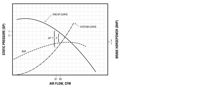
Figure 7 is a fan performance curve showing the Static Pressure (SP) curve and the brake horsepower (bhp) curve. Imposed over these performance curves is a system curve, which represents the resistance of all components in the collection system (hoods, ducting, collector, etc.) less the eventual increased pressure drop across the filter media.

If the design airflow is Q1 with a design ∆P1 and high-performance filter bags are installed that operate at a reduced pressure drop ∆P2, the static pressure at the fan inlet is reduced to SP1, resulting in an increased flow Q2 and an increase in horsepower bhp2 in Figure 8. A mechanical change in the fan system is required to return the flow to the design flow Q1.
One way to reduce the airflow to the original Q2 value, is to simply close a damper to replace the static resistance as illustrated in Figure 9. That reduces the airflow to the original level, but it also returns the bhp to the original level. In effect, the damper is creating a new system curve as shown in Figure 10. This does not accomplish the objective of reducing energy.


To realize the potential energy savings, the bhp requirement must be reduced, and this requires a change in rotational fan speed. The two ways of changing fan speed are variable speed motor drives and simple belt and sheave changes.

If the system has not been measured, a fan curve is not available, or the system flow is variable, the most efficient solution is likely a Variable Frequency Drive (VFD). A VFD can provide an infinite number of fan SP curves and corresponding bhp curves as shown in Figure 11. By simply dialing in the speed that gives desired flow, you can reap the benefits of the changes in brake horsepower.
Remembering the third Fan Law: For a fixed system, the bhp decreases as the cube of the change in speed.
- A 5% decrease in speed results in a 14% energy savings 0.953 = 0.86
- A 10% decrease in speed results in a 27% energy savings 0.903 = 0.73
- A 12% decrease in speed results in a 32% energy savings 0.883 = 0.68
The downside is VFDs are more costly to purchase than a simple belt and sheave change. For a 40hp system, a free standing VFD may cost between $5000 and $5500 and require two electricians a half day to install – an amount that can still achieve satisfactory payback in many situations.
For a fixed system without requirements for variation in airflow, a simple belt and sheave change on the fan drive is all that is required. The change in speed returns the flow to the original Q1 value and reduces the power requirement from bhp1 to bhp2as shown in Figure 12. The fixed speed change provides 100% energy recovery and is inexpensive. For the example system with a 40hp motor, the cost is about $300 and will require two maintenance men about half day to install.

Case History
A large grain handling and oil seed processing facility in southern USA had 35 baghouse collectors with fabric filters in the facility. Under pressure to reduce energy cost, and after much research into performance filter media, a decision was made to fit one collector with hydroentangled filter media. The intention was that the new media could reduce the pressure loss across the collector by 2”wg, and the resulting energy savings with all 35 collectors fitted with this media would be significant.
Figure 13 shows the data for the analysis. The airflow was set at 12,900 cfm. The needle felt pressure drop was 5-inches wg and the hydroentangled fiter bags stabilized at 3-inches wg. The fan was a radial blade fan with an efficiency of 63%. An electric transmission/motor efficiency of 90% was used. The facility operates 24 hours per day, 7 days a week, 51 weeks each year. Their electrical cost was $0.09 per kW hour.

In addition to stabilizing at lower pressure drop, the hydroentangled filter elements also had twice the filter life. When the plant manager calculated everything (labor savings from fewer filter changeouts, the incremental cost of the drive change and the increased cost of the filter bags) the payback time was 3.8 months.
By simply purchasing and installing the hydroentangled bag filters and re-sheaving for a lower speed, the facility determined they could potentially save over $77,000 a year if all 35 dust collectors were retrofitted.
Summary
Air has weight, and considerable energy is used in moving air within industrial ventilation systems. In order to minimize the energy cost and thus reduce the cost of the product, good engineering judgment must be exercised when designing new systems and alternative systems must be considered. For existing systems, look at alternative products like bags with enhanced filter finishes, advanced performance media, and/or innovative filter media configuration with the goal of reducing pressure loss through the system. All these possible solutions may represent a higher initial cost, but when the energy savings is considered, any can provide overall long term savings.