Most thermal spray operations utilize a dust collection system to manage over-sprayed compounds (dirty, dust-laden air), but the dust collection system will only capture dust that reaches the filters. Proper airflow design, which is critical to ensuring the capture and transport of airborne particulate or dust control, is a challenge in thermal spray cells. This article discusses this issue and offers some proven strategies for ensuring it.
Proper System Design
Thermal spray dust control ventilation systems typically include ducts to transport dust-laden air to a dust collector and a fan to move the air through the system. An important part of the ventilation system design is the strategy used to capture dust in the thermal spray cell itself.
Simply increasing the airflow through the cell may not substantially increase the capture of dust, and this approach typically wastes energy. With an analysis of the cell’s layout, the makeup air source location, and the thermal spray target position, it is possible to dramatically improve the capture and exhaust of overspray dust.
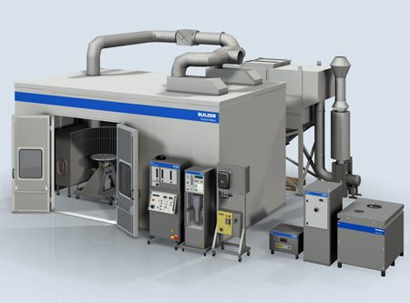 Reproduced by permission of Sulzer Metco
Makeup air system
First, consider the makeup air entering the enclosed thermal spray cell (booth). Ultimately, all the dust-laden (dirty) air removed from the booth by the dust collector must be replaced by air drawn back into the booth. Makeup air is either drawn through openings in the thermal spray booth itself, or through a dedicated makeup air unit usually from outside the building that then delivers it straight to the booth through ducts.
The design of the makeup air system can be critical to the design of the dust collection system because it may cause the thermal spray booth to be under negative (vacuum) pressure or positive pressure. A slight vacuum within the booth can help avoid unexpected positive pressure conditions while the dust collector is pulse cleaning.
During pulse cleaning of your filters, short blasts of reverse air can cause slight increases in the pressure within the thermal spray booth. This increase in pressure can potentially pop open an access door and accidently activate the safety limit switches on the door, which creates an inadvertent emergency stop of the spray process. Booth manufacturers should be consulted on the amount of vacuum that can be applied to their thermal spray cell.
One strategy to manage airflow through the booth is to place makeup air connections opposite the air extraction points on the booth, creating a cross-ventilation air flow pattern. However, since makeup air connections often incorporate sound attenuation devices (silencers), it generally makes sense to place the makeup air connections on top of the booth.
Any connection strategy that can increase the possibility of establishing a cross-ventilation air flow pattern in the booth will be helpful in reducing the potential for dust buildup within the booth.
Extracting dirty air from the booth can be done with a couple of airflow patterns: either downward or horizontal. Although downward airflow patterns work well in dust collector designs, they can present challenges in a booth design.
Downward air flow pattern
In a booth with a downward flow pattern, the floor of the booth becomes a grated opening over a chamber, or plenum. Dirty air is pulled down into the plenum and through ducts to the dust collector. This design has the advantage of using gravity to help draw dust towards the collector and ensures virtually all overspray eventually is exhausted. The challenge is in keeping dust moving with air in that plenum below the floor. With proper design, dust can be successfully drawn through the plenum but, if the plenum design is not done well, dust will settle in the plenum and create a housekeeping challenge.
In a downward flow booth, the velocity of air in the plenum cross section is often kept much higher than the downward velocity in the booth - often in excess of 2,500 feet per minute to ensure dust does not settle in the plenum. This requirement makes effective plenum designs challenging.
Downward flow booths must also be tall enough to allow space for the plenum underneath the floor. It is sometimes possible to use a pit beneath the booth, but booths and their plenums are generally installed above the shop floor.
Horizontal air flow pattern
The other method of pulling dirty air out of a booth is the horizontal air flow pattern. This method of design calls for the plenum to be placed close to where the spraying will be done. It offers the advantage of allowing smaller, more task-focused plenum hood designs. The smaller hoods establish targeted air flow patterns just where the air is most needed - behind the spray target.
The objective of this design is to use the inherent velocity of sprayed materials and the air flow pattern of make-up air entering the plenum to capture as much overspray as possible. This approach typically requires less total air volume to remove the overspray compared with a downward flow booth. Naturally, there are multiple factors involved in this approach, but facilities involved with turbine component spraying have used this method successfully for years.