Technical Article Library
Filter By
Product Group

Industrial Air Filtration
Developing a Comprehensive Management Systems Checklist for NFPA 652 Chapter 8 Compliance in DHAs

Industrial Air Filtration
Mitigation of Combustible Dust in Food and Agriculture

Industrial Air Filtration
Source & Ambient Collection: Solutions for Capturing Weld Fumes

Industrial Air Filtration
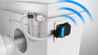
Reduce Costly Line Shutdowns with a Connected Dust Collector
Industrial Air Filtration
The Advantages & Disadvantages of Pre-Coating Pleated Filter Cartridges

Industrial Air Filtration
Applying a Test Standard to Compare Industrial Dust Collectors

Industrial Air Filtration
Best Practices in Dust Collector Hood Design

Engine & Equipment Filtration
Best Practices for Hydraulic Oil Maintenance

Industrial Air Filtration
Can a Dust Collector Solve Silica Exposure?

Industrial Gases & Process Filtration
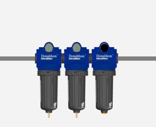
Clean and Dry Compressed Air at the Point of Use

Industrial Air Filtration
Condition-Based Maintenance: 3 Reasons to Use Connected Monitoring for Your Dust Collectors

Industrial Air Filtration
5 Metrics from a Connected Dust Collector That Can Make Your Job Easier

Industrial Air Filtration
Cost Advantages of Point-of-Use Dust Collection in Dump Pit Applications

Industrial Air Filtration
Cost-Effective Dust Collector Placement Strategies

Industrial Gases & Process Filtration
Customize Your Filter Change Schedule

Engine & Equipment Filtration
Dealing with Dirty Diesel: Protecting Engines from Costly Downtime

Engine & Equipment Filtration
Donaldson® Expands Filter Minder™ Connect to Drive Smarter Fleet Maintenance

Industrial Air Filtration
Donaldson Torit® Engineers Filter Growth Through Technology

Industrial Air Filtration
Dust Collection Preventative Maintenance – 5 Tips to Help Keep Your Processing Running Smoothly

Industrial Air Filtration
Dust Collector Exhaust Air - 3 Reasons to Pay Attention

Industrial Air Filtration
Choosing the Right Dust Collector for Coal Handling Systems

Engine & Equipment Filtration
How to Keep Modern Diesel Engines Running Strong in Cold Weather
Engine & Equipment Filtration
Filter Minder™ Connect: Giving Your Fleet a Voice

Engine & Equipment Filtration
Proper Sampling Techniques for Fuel and Oil

Engine & Equipment Filtration
Understanding Full-Flow vs. By-Pass Lube Filtration

Engine & Equipment Filtration
Liquid Spin-On Filters: Installation and Maintenance Made Easy
Engine & Equipment Filtration
How to Prevent Fuel Quality Issues in Bulk Diesel Storage

Engine & Equipment Filtration
Small Improvements in Air Filtration Deliver Big Savings for Your Fleet

Engine & Equipment Filtration
Understanding Hydraulic Contamination in Modern Equipment

Engine & Equipment Filtration
Keep Your Hydraulic System Clean: Hose Maintenance Tips That Matter

Engine & Equipment Filtration
The Importance of Clean Fuel

Engine & Equipment Filtration
Safeguard Your Diesel Fuel and Prevent Costly Injector Failures
Engine & Equipment Filtration
Why Safety Filters Matter for Engine Protection

Engine & Equipment Filtration
The Growing Threat of Hard Particle Contamination in Modern Diesel Engines

Engine & Equipment Filtration
How to Avoid Fuel Additive Incompatibility and Glycerin Contamination

Engine & Equipment Filtration
What Do Hydraulic Filters Really Do?

Engine & Equipment Filtration
Overcoming the Challenges of Water in Diesel Fuel
Engine & Equipment Filtration
The Hidden Threat in Diesel Fuel: Contamination
Engine & Equipment Filtration
Smarter Fleet Maintenance with Filter Minder™ Connect

Engine & Equipment Filtration
How Can You Minimize Hydraulic System Contamination?
Engine & Equipment Filtration
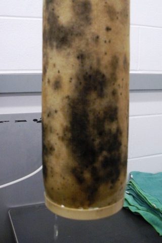
Microbial Bacteria in Diesel Fuel: What You Need to Know

Industrial Gases & Process Filtration
HACCP Planning: A Guide for Managing Contamination Risks in Utilities

Industrial Gases & Process Filtration
What to Filter as You Manufacture Pet Food

Industrial Gases & Process Filtration
Safeguarding Fermentation Feedstock in Your Alternative Protein Operation
Industrial Gases & Process Filtration
How to Meet the SQF Compressed Air Standard

Industrial Air Filtration
Mist Collection: Fundamentals & Applications

Industrial Air Filtration
Mitigating Combustible Dust Risks in Powder Processing

Industrial Air Filtration
Stakeholder Input: Essential for Effective Dust Hazard Analysis
Industrial Air Filtration
Ultra-Web® Filter Media Technology

Industrial Air Filtration
Managing Fluid Mist Hazards
Industrial Air Filtration
Optimizing Dust Collector Filter Cleaning Technology

Industrial Air Filtration
Laser and Plasma Applications: Selecting a Dust Collection System

Industrial Air Filtration
My Dust Collector is Leaking
Industrial Air Filtration
Insufficient Airflow at the Hoods
Industrial Air Filtration
Using MERV Ratings to Determine the Effectiveness of Industrial Dust Collectors

Industrial Air Filtration
Taking the Mystery Out of Industrial IoT

Industrial Air Filtration
Minimizing Downtime and Lost Production in Baghouse Operations
Industrial Air Filtration
3 Things a Connected Dust Collector Can Tell Environmental Health & Safety Leaders

Industrial Air Filtration
5 Combustible Dust Misconceptions

Industrial Air Filtration
Think Twice Before Wet or Dry Cleaning Your Dust Collector Filters
Industrial Air Filtration
Optimizing Airflow on Dust, Mist and Fume Collection Systems

Industrial Air Filtration
Mist Collector Cleaning Best Practices

On-Compressor Filtration
Energy Use in Air Compressors Impacted by the Efficiency of Three Filters

Industrial Air Filtration
Pleated Bag Filters: Problem Solvers in the Grain, Feed & Seed Industries

Industrial Air Filtration
6 Tips to Properly Maintain Your Dust Collector

Industrial Air Filtration
Starting a Dust Hazard Analysis and Reducing Combustible Dust Risk in Chemical Processing

Industrial Air Filtration
Sizing Ductwork for Dust Collection Systems

Industrial Air Filtration
Optimizing Dust Collection in the Food Industry

Industrial Air Filtration
Driving Optimal Performance From Your Weld Fume Collector

Industrial Air Filtration
Reducing Bridging in Dust Collector Hoppers

Industrial Air Filtration
Understanding Conveying Velocities to Save Money on Dust Collection

Industrial Air Filtration
8 Tips for Planning and Executing Dust Collection Projects

Industrial Air Filtration
What to Look for in a Weld Fume Extraction System
Industrial Air Filtration
Troubleshooting Dust Collector On-Demand Cleaning Systems

Industrial Air Filtration
Dust Control in Grain Elevators and Terminals

Industrial Air Filtration
Metal Dust Hazards: Igniting Awareness and Safety
Industrial Air Filtration
Top 5 Reasons a Fine Fiber Performance Layer Filter is Worth It

Industrial Air Filtration
What Is a Baghouse Dust Collector?

Industrial Air Filtration
Save Money on Filters by Maintaining Dust Collector Discharge Devices

Industrial Air Filtration
Hexavalent Chromium: What You Need to Know

Industrial Air Filtration
5 Ways the Contura Pulse Controller Simplifies Dust Collector Management

Engine & Equipment Filtration
Combining Data for Smarter, More Efficient Fleet Management

Industrial Gases & Process Filtration
Preventing Moist Air Contamination in Food and Beverage Processing

Industrial Gases & Process Filtration
Humidity: A Mysterious Contaminant – How to Filter It and Why

Industrial Air Filtration
4 Factory Priorities a Smart Dust Collector Can Tackle
Engineered Systems
Lube Filtration Strategies

Industrial Air Filtration
Unlock Baghouse Performance Potential: 5 Reasons to Embrace Hydroentangled Baghouse Bags

Industrial Air Filtration
6 Things to Consider Before You Purchase an Ambient Weld Fume Collector

Industrial Air Filtration
The Case for Horizontal Filters in Cartridge Dust Collectors

Industrial Gases & Process Filtration
Frequently Asked Questions – Process Filtration
Engine & Equipment Filtration
Extend Air Filter Life with the Right Pre-Cleaner

Engine & Equipment Filtration
6 Common Types of Hydraulic Fluid Contamination—and How to Prevent Them

Industrial Gases & Process Filtration
Recommended Replacement Schedule: Preventative Maintenance

Engineered Systems
What Do Primary and Secondary Filters in Your Fuel System Do?

Membrane Filtration
Advantages of Venting Technology

Membrane Filtration
3 Factors to Consider When Specifying a Venting Solution

Industrial Air Filtration
ISO 16890: The Global Standard for Air Filtration

Industrial Gases & Process Filtration
Protect Your Non-Alcoholic Beverage Plant from Contamination

Membrane Filtration
Protecting Powertrain Components: How Venting Has Improved
Engineered Systems
Testing Capabilities and Filtration Technology

Industrial Air Filtration
Combustible Metals Dust: Three Points to Know

Membrane Filtration
Advantages of ePTFE-Reinforced Composite PEM in Fuel Cell Stacks

Industrial Air Filtration
What Is the Internet of Things (IoT) and How Can It Help Filtration?
Industrial Gases & Process Filtration
Filter Replacement Intervals – 4 Reasons Why They Matter

Industrial Air Filtration
Where to Begin: Industrial IoT Adoption in Your Plant

Engineered Systems
The Importance of Lube Filtration

Engineered Systems
New Alpha Test Standards for Assessing Hydraulic Filters

Engine & Equipment Filtration
When to Change Your Air Filter: Why Restriction Matters More Than Appearance

Membrane Filtration
5 Design Considerations When Selecting An Optimized Battery Venting Solution

Engineered Systems
Aftertreatment System Designs Will Evolve to Meet Customer and Emissions Requirements
Industrial Air Filtration
Combustible Dust Mitigation for Food Manufacturing Facilities

Membrane Filtration
Keeping Outdoor Lights on with State-of-the-Art Vents

Engineered Systems
Transmission Filtration Systems Are More Than Just Filters

Industrial Air Filtration
When to Tackle an Industrial IoT Upgrade
Industrial Gases & Process Filtration
Improved Technology in Liquid Filtration
Industrial Gases & Process Filtration
Areas to Filter in a Pharmaceutical Process
Industrial Gases & Process Filtration
Steam Filters: Three Times When Stainless Steel is a Better Choice

Engineered Systems
Pre-configured or Custom? How to Choose the Right Air Intake System

Engineered Systems
Strategic Filtration of Hydraulic Circuits

Engineered Systems
Filters Optimize Hydraulic System Function

Engineered Systems
5 Steps to Choosing a Standard Air Cleaner

Engineered Systems
Fuel’s #1 Enemy Is All Wet

Industrial Gases & Process Filtration
Ensuring Effective Filtration Performance and Energy Savings

Engineered Systems
Under Pressure: Cyclic Flow Filtration
Industrial Gases & Process Filtration
Three Tips for Filtering Compressed Air

Engineered Systems
The Evolution of Fuel Filtration

Industrial Air Filtration
5 Ways to Manage Dust Collector Costs and EHS Reporting Costs
Industrial Air Filtration
Electric Vehicle Battery Makers and Dust Collection

Industrial Air Filtration
What are Welding Fume Extractors and Their Benefits?

Industrial Air Filtration
Reduce Energy Costs Associated with Industrial Fans

Industrial Air Filtration
Gigafactory Dust Collection

Industrial Air Filtration
What Size Dust Collector Do I Need?

Industrial Air Filtration
Maintain Your Aging Dust Collector with Connected Monitoring

Industrial Air Filtration
Enhance Your Maintenance Program with Dust Collector Monitoring and Service

Industrial Air Filtration
Donaldson's Strategic Acquisition of Torit: A Catalyst for Industrial Filtration Technology
Industrial Air Filtration
3 Ways to Help Reduce Your Dust Collector’s Energy Use

Industrial Gases & Process Filtration
Why Purified Compressed Air and Gas Matter in Glass Production

Gas Turbine Filtration
Three Pillars of Gas Turbine Filtration: Ranking Performance Priorities

Industrial Gases & Process Filtration
Two-Pressure Compressed Air in Glass Production

Industrial Air Filtration
The 3 E's of Managing Dust Control Performance: Exposure, Efficiency and Emissions
Engineered Systems
Transmission Control: We Have Filtration

Industrial Gases & Process Filtration
CO2 Capture and Purification: Why Filtration Matters
Industrial Gases & Process Filtration
6 Reasons Why Desiccant Dryers Are the Smarter Choice for Compressed Air Treatment

Industrial Gases & Process Filtration
Extend Final Filter Life with Donaldson’s Filtration Expertise for Wineries

Industrial Gases & Process Filtration
Brewery Filtration Troubleshooting: Trap Filter Failures Explained

Industrial Gases & Process Filtration
How to Prevent Flavor Degradation in Natural Mineral Water Products

Industrial Gases & Process Filtration
Avoid Bottled Water Production Downtime with Donaldson Filtration Solutions

Industrial Air Filtration
Advantages of a Complete Dust Collector Filter Change Out

Industrial Air Filtration
Collecting Pharmaceutical Dust
Industrial Gases & Process Filtration
New Market Opportunities for High Purity CO2

Industrial Air Filtration
Adjusting Dust Collector Fan Dampers to Save Time and Money

Engine & Equipment Filtration
6 Things You Should Know About Your Hydraulic Fluid

Engine & Equipment Filtration
5 Quick Facts About Fuel Quality and Filtration

Engine & Equipment Filtration
How to Prevent Water from Entering Your Air Intake System
Engineered Systems
Rethinking the Hydraulic Reservoir

Industrial Air Filtration
Dust Collector Repair vs. Replace?

Industrial Gases & Process Filtration
Leveraging Filter Technology to Increase Energy Savings in Your Plant

Engine & Equipment Filtration
Protecting Diesel Engines in Cold Weather: What You Need to Know

Engine & Equipment Filtration
Water is the Hidden Enemy of Diesel Engines

Industrial Gases & Process Filtration
Sterile Air - What It Is & Why It Matters

Engine & Equipment Filtration
The Degradation of Fuel Over Time

Industrial Air Filtration
Differential Pressure: What It Is and Why You Should Care

Industrial Air Filtration
Conquer Sticky Dust: Effective Dust Control Solutions for Pet Food Production

Engine & Equipment Filtration
Dirty Diesel: A Hidden Threat to Modern Engines

Gas Turbine Filtration
Research Shows Donaldson Gas Turbine Filters Continue to Surpass Industry Standards

Industrial Air Filtration
Dura-Life™ Media Technology

Industrial Gases & Process Filtration
Protect Your System from Humidity This Summer

Gas Turbine Filtration
Quick Lock Yoke Filter Retention System - Eliminate Bypass for Gas Turbines and Deliver More Power

Industrial Air Filtration
Understand Your Weld Fume Hazards

Industrial Air Filtration
Pleated Bag Filters: A Baghouse Dust Collection Problem Solver

Industrial Gases & Process Filtration
Sterile Air Checklist for Fermentation Processors

Industrial Gases & Process Filtration
Avoiding Product Spoilage When in Storage

Industrial Air Filtration
Keep Your Product Recovery System Sterile

Lowering Total Cost of Ownership in Mining, Aggregates, and Energy

Industrial Gases & Process Filtration
3 Filter Factors for Lactose-Free Processing Plants

Industrial Gases & Process Filtration
Navigating the 3-A Culinary Steam Guideline

Engineered Systems
Designing, Testing, and Manufacturing Exhaust and Emissions Systems

Industrial Gases & Process Filtration
Green hydrogen: How efficient filtration solutions contribute to clean energy production

Membrane Filtration
Protecting Battery Enclosures with Dual-Stage Venting

Industrial Gases & Process Filtration
3-A Sanitary Requirements – Does My Filter Comply with the Standard?

Industrial Gases & Process Filtration
Why Expertise Matters in Food & Beverage Processing
Industrial Gases & Process Filtration
Certified Breathing Air Purification for Industrial and Medical Applications

Managing Compressed Air for Industrial Dust Collectors
Industrial Gases & Process Filtration
Compressed Air Quality Improvements

Industrial Gases & Process Filtration
Energy-Saving Filtration Technology
Today’s New Battery Vents are Engineered for Tomorrow’s Challenges

Membrane Filtration
Elements, Engineering, and Expertise: The 3 E's to Successful Electric Drive Module Venting

Engine & Equipment Filtration
Air Filter Efficiency: What It Means and How It's Measured

Engine & Equipment Filtration
Best Practices for Clean Diesel: Protect Your Fuel, Equipment, and Bottom Line

Replacing Hydraulic Filters: What You Should Know

Industrial Air Filtration
Industrial Dust Collector Filter Types

Industrial Gases & Process Filtration
Hard Seltzer Filtration Solutions

Industrial Air Filtration
PowerCore® Filter Media Technology

Industrial Air Filtration
Navigating the Complexities of Industrial Dust Collector Troubleshooting

Industrial Air Filtration
Thermal Cutting Dust Collection - Balancing the Variables

Industrial Air Filtration
Wet Machining: Control Air Quality by Effective Smoke Collection

Industrial Air Filtration
Thermal Spray Dust Collection - Hood Design

Industrial Air Filtration
Efficient Control of Thermal Spray Dust Collectors

Industrial Air Filtration
Filter Media in Bags and Cartridges: Save Energy with Advanced Technology
Industrial Gases & Process Filtration
The Role of Housings and Filter Elements in Reliable Compressed Air and Gas Filtration

Industrial Gases & Process Filtration
Dry Air Keeps Dust Collectors at Peak Uptime

Industrial Air Filtration
The Core of Dust Collection: Understanding Fan Design

Industrial Air Filtration
5 Things You Should Know about Dust Collection Filter Media

Industrial Gases & Process Filtration
6 Overlooked Factors to Consider When Choosing a Compressed Air Dryer

Industrial Air Filtration
Beyond Capex: Mastering Dust Collector Total Cost of Ownership

Industrial Gases & Process Filtration
Operational Efficiency Roadmap in Beverage Manufacturing

Industrial Air Filtration
Mist Collection System Design

Industrial Gases & Process Filtration
Advanced Solutions for Oil-Free Compressed Air and Gas
Industrial Gases & Process Filtration
Clean, Reliable Compressed Air: Understanding Key Filtration Stages

Industrial Gases & Process Filtration
ISO 8573-1: Are You Meeting the Standard or Just Guessing?

Industrial Air Filtration
Six Things to Consider When Purchasing a Dust Collector

Engine & Equipment Filtration
3 Reasons You Should Replace Your Air Dryer

Engine & Equipment Filtration
Vacuator™ Valves: Small Part, Big Impact

Frequently Asked Questions about Diesel Fuel
Engine & Equipment Filtration
Common Fuel Contaminants—and How to Keep Them Out of Your Engine
Engine & Equipment Filtration
Understanding ISO Cleanliness Codes
Engine & Equipment Filtration
Fuel Filter Plugging: How to Spot It and What You Can Do About It
Engine & Equipment Filtration
Understanding Beta Ratings in Liquid Filters

Industrial Gases & Process Filtration
Why Monitoring Compressed Air Dryer Performance Is Critical for Industrial Efficiency

Industrial Gases & Process Filtration
Reducing Costly Biofilm Build-up in Reverse Osmosis Membranes

Industrial Gases & Process Filtration
Helping Protect Automation and Robotics with Clean, Dry Compressed Air

Industrial Gases & Process Filtration
Why Clean, Dry Instrumentation & Control Air Is Critical for Industrial Manufacturing

Industrial Air Filtration
5 Things to Consider When Purchasing a Baghouse Collector
Industrial Gases & Process Filtration
Why Rate Sterile Air Filters at 0.2 Microns?

Industrial Gases & Process Filtration
Filter Basics for Food and Beverage Processors

Industrial Gases & Process Filtration
Filtering Contaminants to Meet Brewery Regulations

Industrial Gases & Process Filtration
Filtration Design for Sterile Compressed Air & Culinary Steam Regulatory Compliance

Industrial Gases & Process Filtration
Filtration for Fermented Plant Based Proteins