Extend filter life. Conserve energy. Save money.
Optimizing airflow control in your dust, mist and fume collector offers important benefits, including extended filter life, increased energy conservation and overall cost savings. Additionally, in many applications, the right dust collector airflow is critical to quality. Too much airflow in stainless steel welding can pull shield gas away from welds, resulting in low quality seams, while too little airflow can expose operators to hazardous compounds such as hexavalent chromium.
In material processing applications where combustible dust may be a concern, the correct airflow is especially critical, as too much airflow can pull valuable product out of the process into the waste stream, but too little airflow can allow dust to escape the process and potentially increase the combustible dust hazards in the facility.
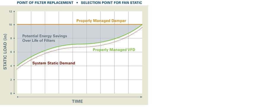
The impact of airflow on filter life is often overlooked during operations, but can be significant when filters are first installed. Operationally, the low initial pressure resistance of fresh filters can result in increased flow through the system, which may not be a problem for operations, but can dramatically reduce the total operational life of the filters (often by more than half). An airflow control strategy to maintain design airflow will extend total filter performance life.
Energy savings and overall costs vary by airflow control strategy and are outlined in the following discussions.
The traditional way to control airflow is to manually adjust an outlet damper on the collector’s fan. This can be an effective means of airflow control if it is done properly and adjusted often, as conditions in the system change over time. Unfortunately, not all operators know how to adjust an outlet damper properly, and, as a result, it is not unusual for a plant to see shorter filter life, compromised product quality, and increased housekeeping and operating cost as a result.
Alternative approaches to optimize airflow control include:
- Use of an inlet vane damper
- Modifying the fan by replacing the sheaves
- Use of an digital control system with variable frequency drive (VFD)
Following are the pros and cons of each:
Inlet Vane Damper
An Inlet vane damper can offer energy savings by pre-spinning the air as it enters the fan so the fan does not work as hard. This option provides some horsepower and energy savings, with a relatively low capital cost. The disadvantage of the inlet vane damper is the damper still requires manual adjustments, as system conditions change over time, and there is a potential maintenance requirement for the damper.
Modify the Fan by Replacing the Sheaves on the Motor and/or Fan
Another option for controlling the airflow is to actually modify the fan rotational speed by installing new sheaves on the motor and/or fan. The lower rotational speed of the fan reduces the break horsepower, saving operational costs. This modification may be cost effective, however, it is not easy to adjust fan speed across a wide range of conditions. Additionally, it usually involves the continued use of a damper for fine tuning airflow, as the system conditions change over time.
The strategy of replacing the sheaves is not uncommon, as there are usually conservative factors applied during system designs to maintain velocities in the system. Identifying and removing conservative design estimates can provide some energy savings. Designers often include an additional inch or two of static capacity in a fan for unexpected resistance in the duct design.
An example of conservative design practice would be the grain industry, where many designers use 4,500 feet per minute as a minimum conveying velocity because the system static changes (as dust builds up on the filters). Operators may not adjust the outlet damper (assuming there is one) in an effort to avoid dust from collecting in the duct, which is a combustible dust and weight hazard. Systems designers often use conservative, higher-than-required velocities to compensate for unexpected reductions in airflow.
Digital Controls with Variable Frequency Drive (VFD)
The most effective way to optimize airflow in a collector is with a digital control using a variable frequency drive (VFD).1 This method monitors a system parameter, such as velocity pressure in a duct or static pressure at the collector inlet - both of which can be directly tied to a desired operational parameter like volumetric flow rate. The digital control system with a VFD can monitor the status of the system and automatically adjust airflow as conditions in the system change over time.
The primary benefit of a digitally controlled VFD is that it automatically maintains design airflow as system conditions change. The design airflow is established and the digital controller is set for the control variable by a technician during initial start up. This eliminates any later need for an operator to manually adjust a damper as system conditions change (i.e. pressure drop increases as dust builds on the filters). The digitally controlled VFD airflow system helps maintains adequate capture at the hoods, keeping productivity high, leaving product where it is supposed to be in the process, and helping ensure quality air in the workers’ breathing zone. The digitally controlled VFD system also assures consistent conveying velocity, which reduces material buildup in the ducts, minimizing maintenance and potential risks such as fires in the ducts.
A digitally controlled VFD system also produces an energy savings similar to a motor soft-start by reducing peak demand charges. Another benefit of using a digitally controlled VFD is noise reduction. Avoiding excess air volume and associated velocity reduces noise substantially compared to using an outlet damper. A customer running a thermal spray shop stated that after installing a dust collector with this type of system, the noise was so dramatically reduced he plans to retrofit all of his dust collectors with digitally controlled VFDs.
A drawback to digitally controlled VFD systems has been their capital costs. When considering a VFD control system, look for rebates on sites such as DSIRE™ (Database of State Incentives for Renewables & Efficiency) and local electric and gas companies. These incentives can often be substantial, offsetting much of the capital cost of a digitally controlled VFD system. It is important to note that some organizations require the application be submitted (and even approved) before a Purchase Order can be issued to purchase the equipment.
Saving Energy via the Electrical Control System and VFD
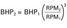
A digitally controlled VFD system can save energy by minimizing the speed (RPM) of the fan to control airflow. This works well because established fan laws include a cubed relationship between the speed of the fan and the brake horsepower or energy consumed by the fan. The formula is shown on the right.
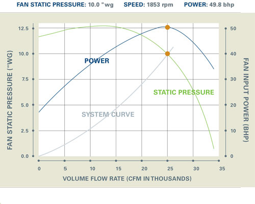
 As an example, a fan sized to deliver 25,000 cubic feet per minute (CFM) at 10 inches water gauge static pressure (10”wg), would use 49.8 brake horsepower (BHP) at 1853 revolutions per minute (RPM).
The annual operating cost of that fan at $0.07 per Kilowatt hour (kWh) for 24/7 operation is $17,000. (It is recommended that you check online for the electric bill rate in your area.)
 Fan curves courtesy of New York Blower Company
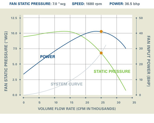
If your system static load averages 7”, rather than the 10”wg needed when the filters are nearing the end of their life, the average speed of the fan (using a VFD) can be reduced to 1680 RPM. At that point, the annual operating cost would only be lower.
For the majority of the operational life of the filters, the fan would cost $12,500 for a difference of $4,500 per year, which is all savings. That equates to $1,500 for each inch of static pressure saved in this system for this fan, and the savings continues year after year.
The same scenario at $0.20 per kWh, generates a savings of $18,000, or $6,000 per inch of static pressure saved each year.
Even a fan curve matching your collector airflow exactly will include one or two inches of additional static pressure to accommodate unexpected obstacles and changes in filter condition. With a system automatically maintaining design airflow, the risk of material in the duct falling out of the airstream is decreased and a less conservative conveying velocity can be selected.
 Design System Static
The Savings Add Up
A system with a VFD air flow controller does cost more initially, but the Return on Investment (ROI) based on energy savings alone is usually less than two years, and this does not include any additional savings resulting from longer filter life and better process control.
Ways to further optimize your system and take advantage of energy savings:
- Use high quality filter media that allows dust to load on its surface, rather than embedding in its depth. This enhances cleaning, lowers pressure drop, and lengthens filter life. Remember each inch of static pressure costs money, and using a surface-loading media can often save one to two inches of average static pressure compared to commodity media.
- Make the following fixes to your system for increased energy savings:
- Remove unnecessary elbows to straighten duct runs,
- Replace any elbows directly ahead of the fan with a well-designed inlet box,
- Replace any T-fittings with classic 30-degree branch entries and redesign or replace any inefficient and/or damaged hoods.
By optimizing the airflow in your dust, fume or mist collector, a VFD air flow controller has proven to be the most reliable option because it delivers extended filter life, conserves energy, and ultimately saves money.